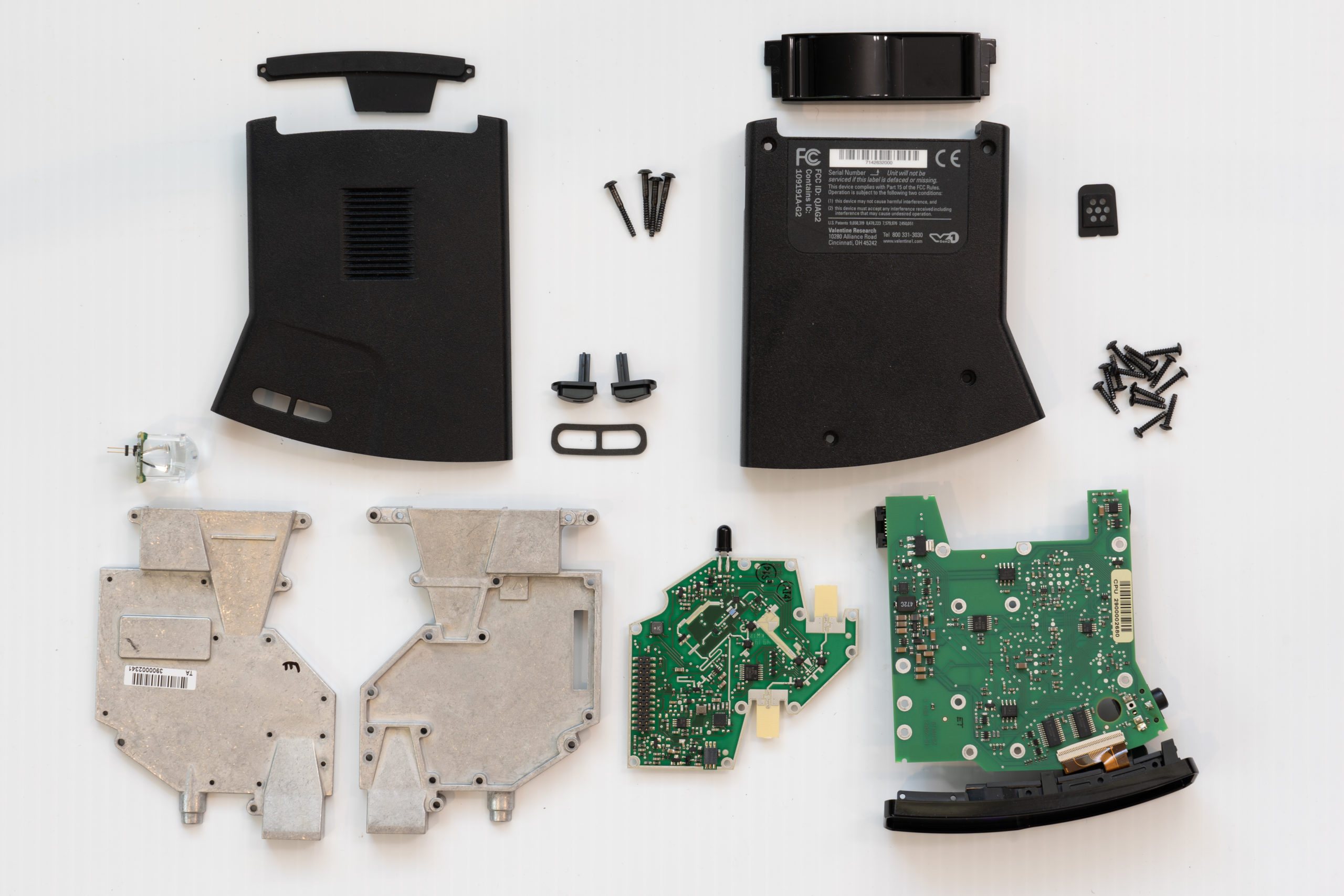
The new Valentine 1 Gen2 is based on a completely new underlying platform than the Gen1 so let’s pop the hood, take the detector apart, and take a closer look at what’s inside. 🙂

V1 Gen2 Teardown
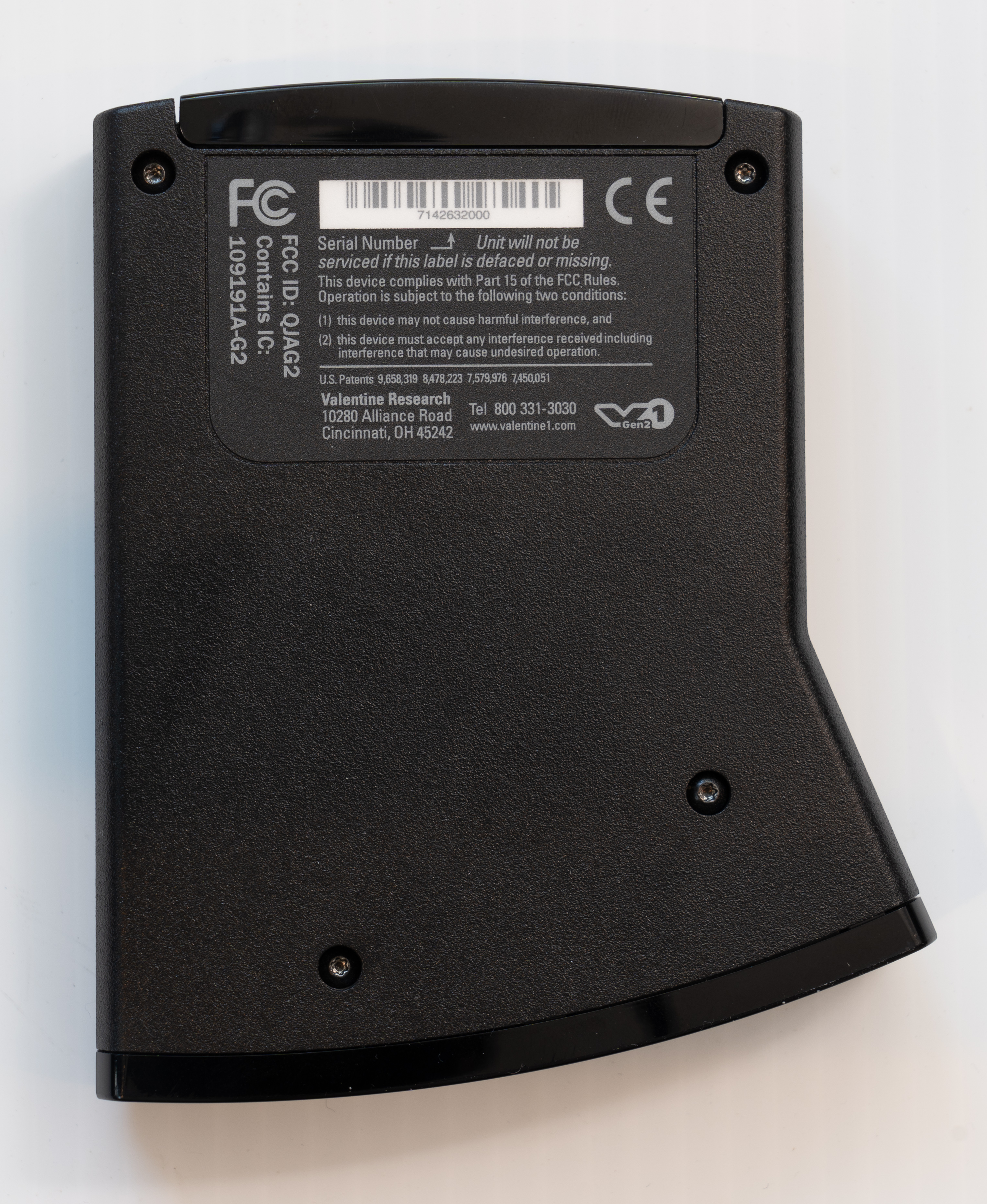
Note: All the photos are available in high res so click on any image to zoom in and take a closer look around, check out part numbers, and see how everything has been laid out. This is a look at my repaired V1 Gen2 after it died.
To open the V1 up, you’ll want a T6 or T7 torx screwdriver. To open the case, use a T7 bit to unscrew the four screws on the bottom.
Then you can carefully remove the top cover.
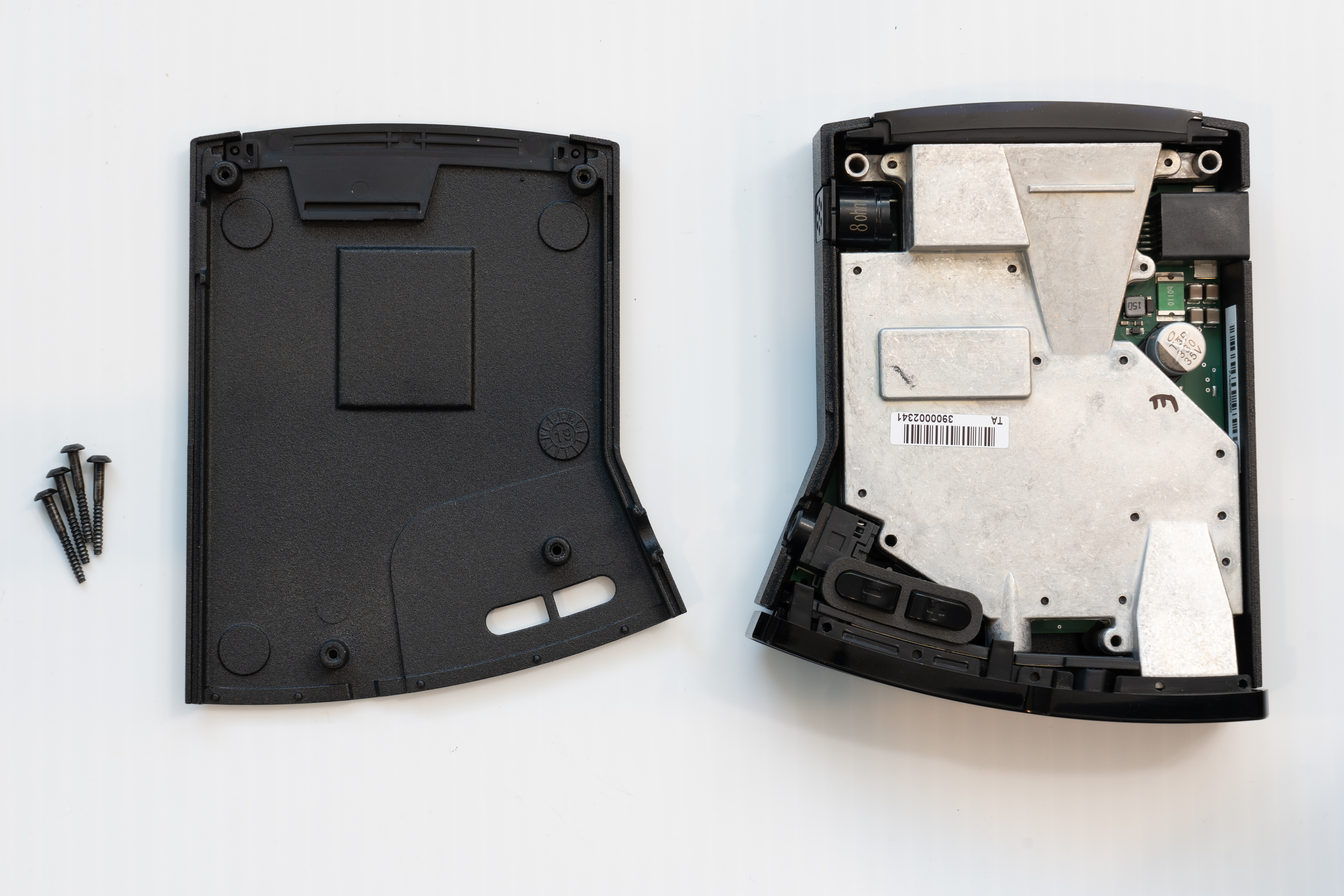
Here’s a closer look at the dual antenna horn casing.
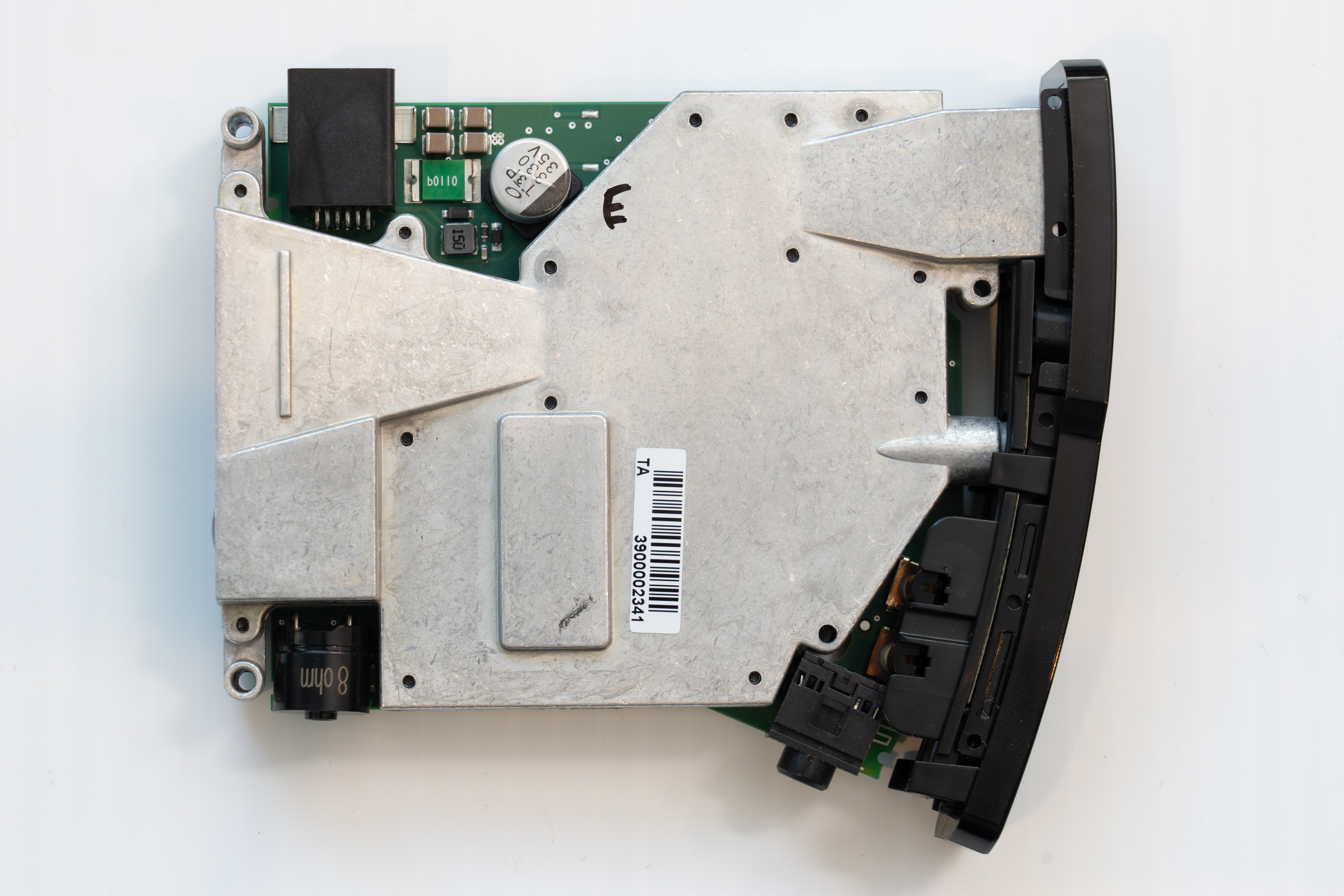
Sliding the internals out of the rest of the case and looking underneath, you’ll find a PCB that connects to the display, buttons, speaker, etc.
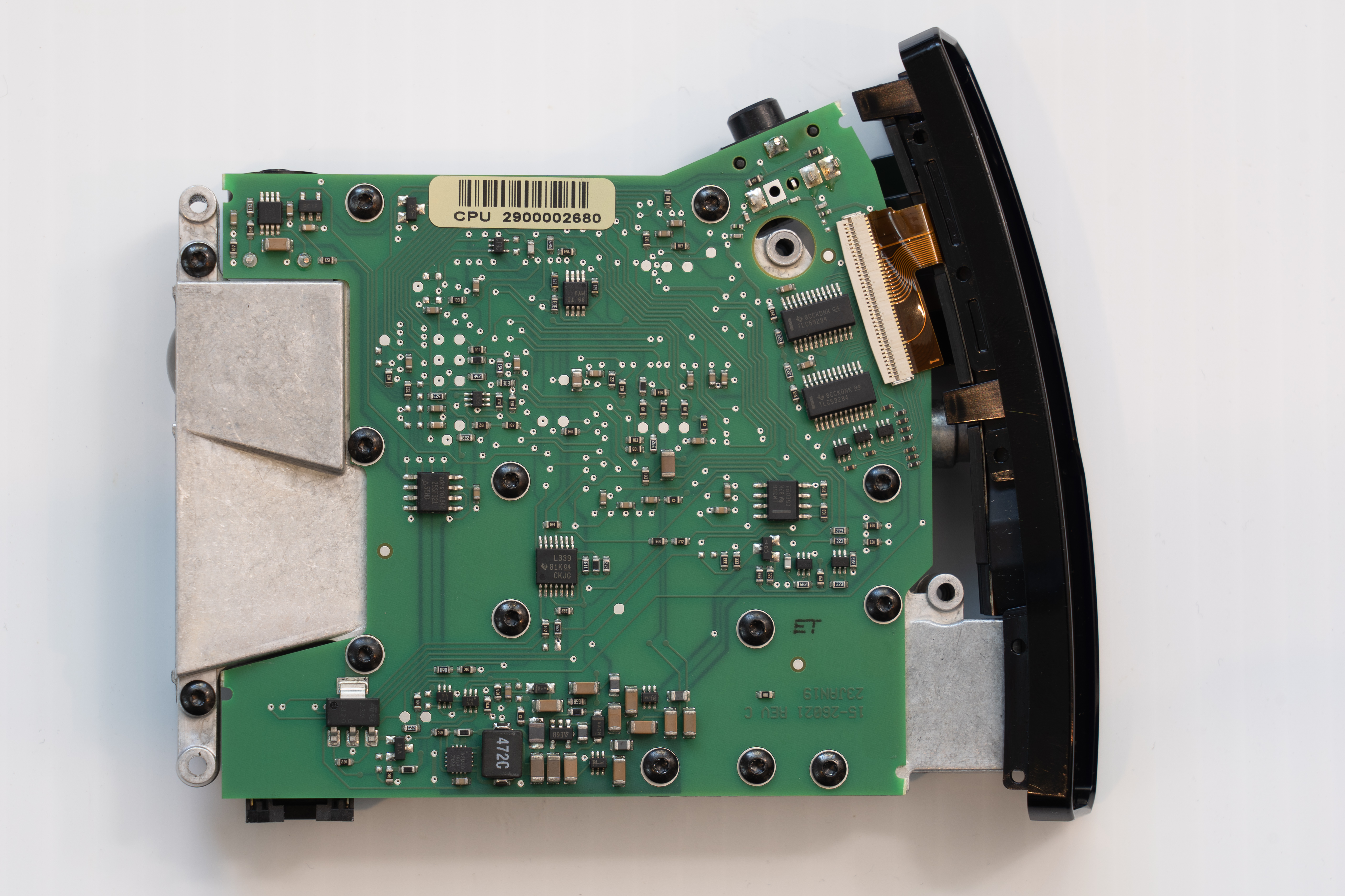
At the bottom you’ll see that this is a Revision C board with a date code of Jan 23, 2019.
There’s a bunch of black T6 screws on that PCB you can unscrew to separate the horn from the PCB.
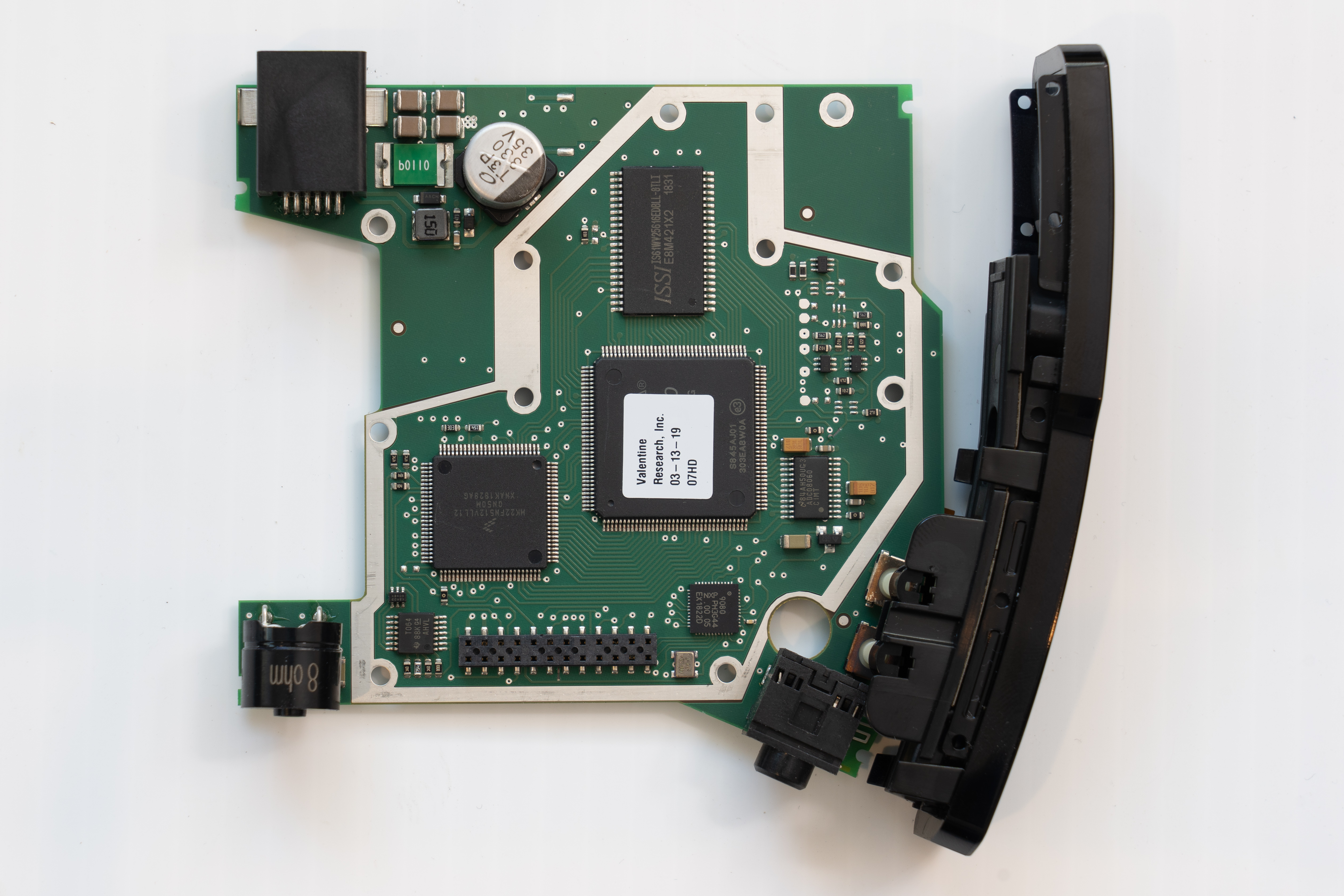
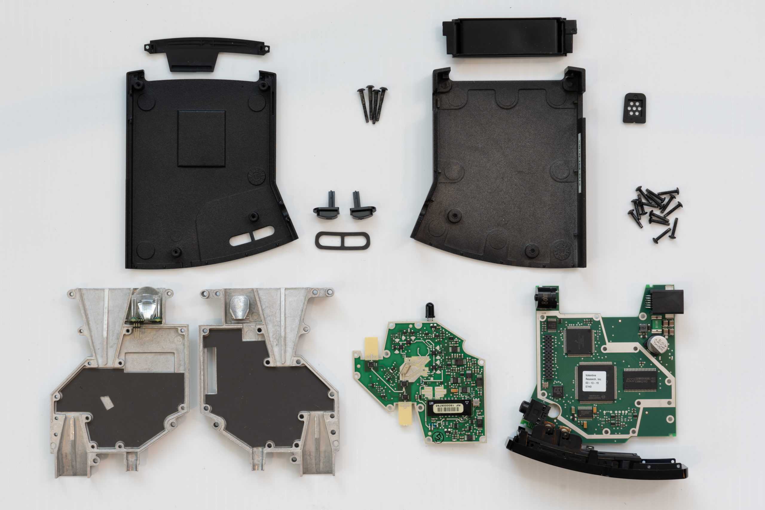
Here’s a look at the other side of the PCB where you’ll find the microcontroller (big square IC on the bottom left), some memory (top center rectangular IC), an ADC (rectangular IC on right near the display), etc. I didn’t remove the sticker to check out the part number of the big component in the center, but my guess is it’s an Altera FPGA.
The speaker is the black round part on the bottom left labeled 8 ohm.
Let’s take a closer look at the horn next and what’s inside.
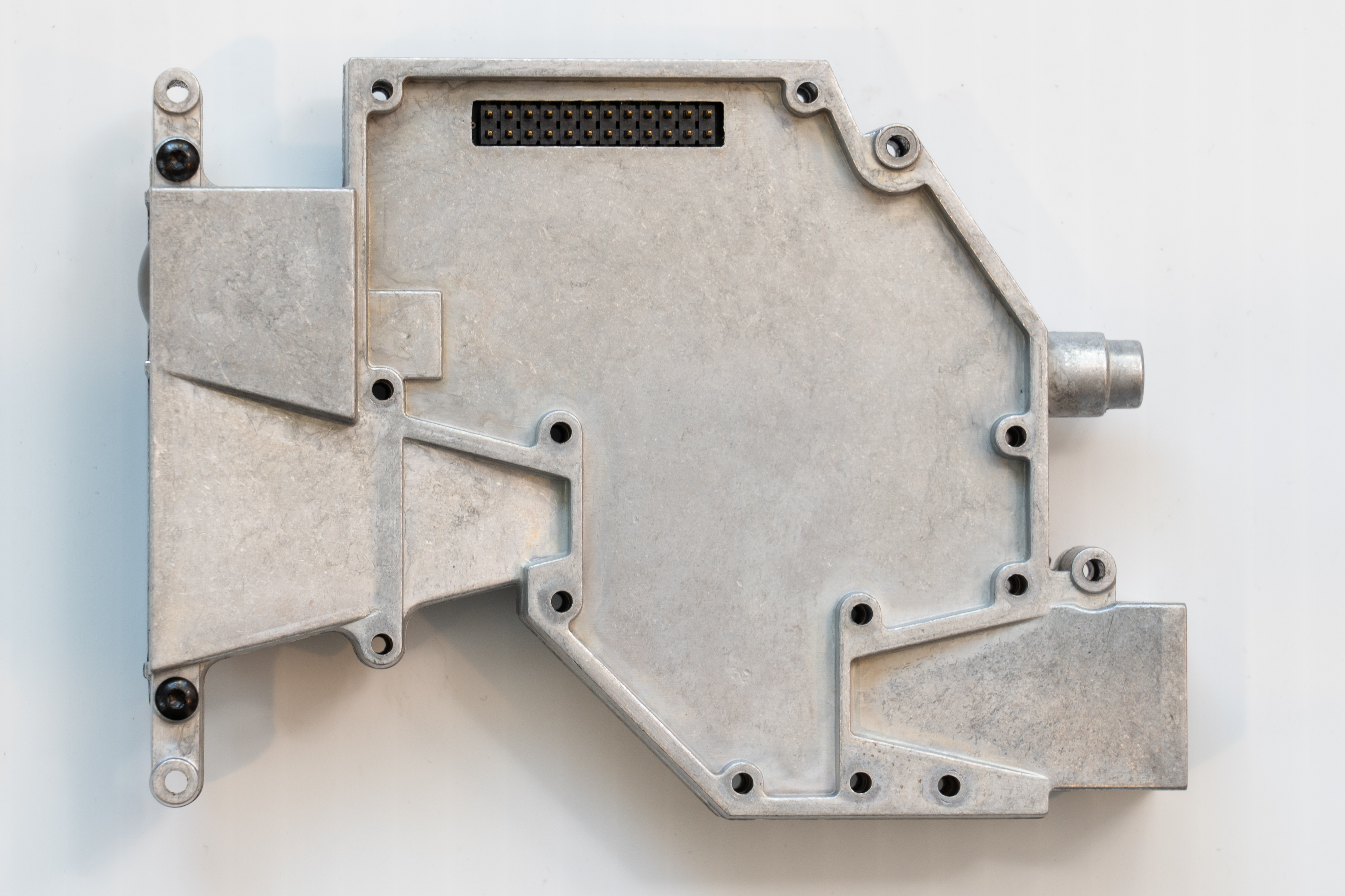
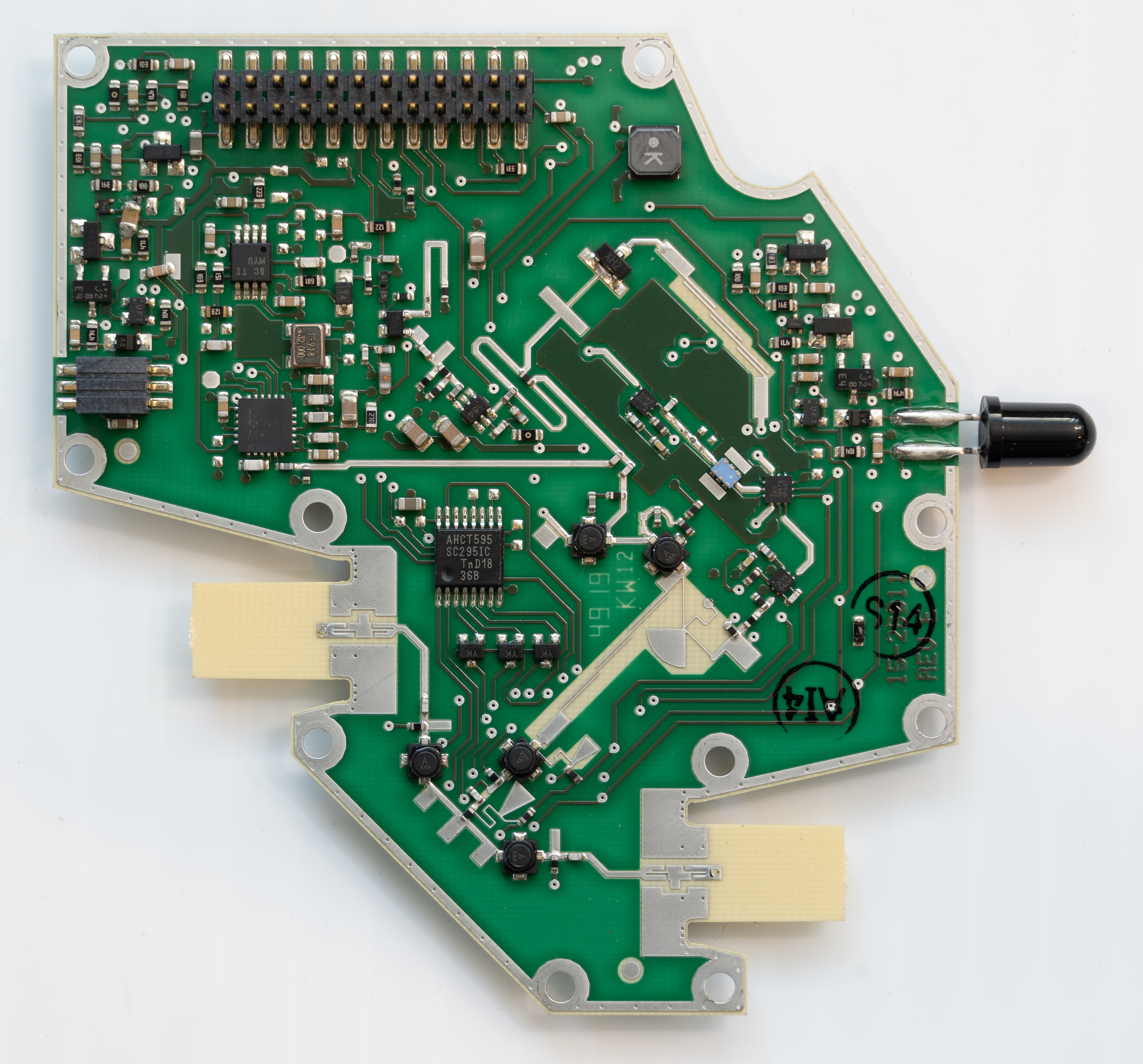
Sandwiched inside the horn is a second RF PCB. At the top of the photo, you’ll see a 24-pin connector coming from the RF PCB that plugs into the outer PCB we were just looking at.
Looking at the photo above, you’ll see the RF PCB as well as the inside of both horns. In the center of each horn you’ll find a ridge running down the center. There’s ridges on both sides of the horn casing as part of the Valentine’s dual ridged waveguide horn patent.
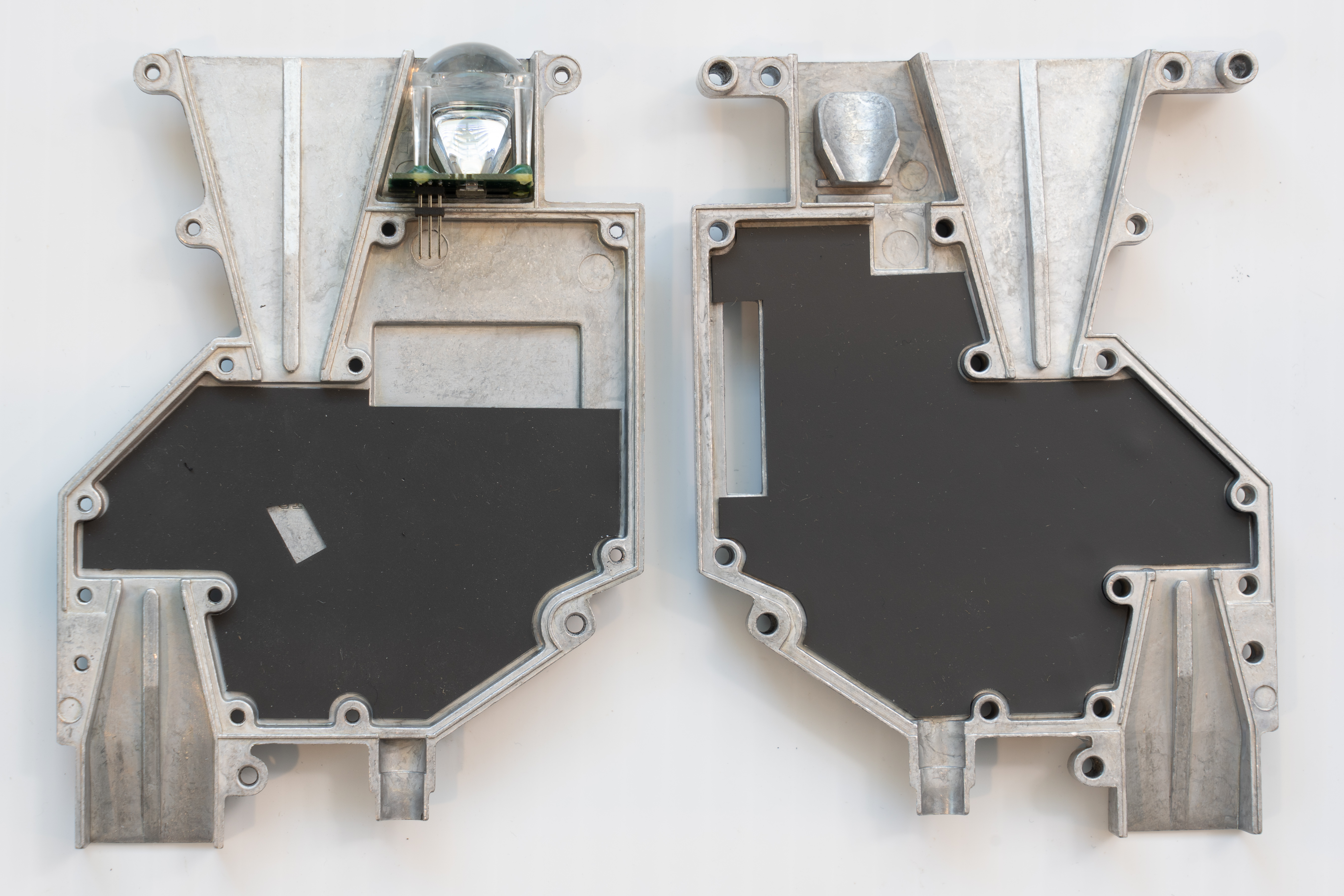
At the top left you’ll also see the big focusing lens for the front laser sensor which is likely a big reason why the V1 has such great laser sensitivity. Then you’ll see the pins that plug back in to the RF PCB.
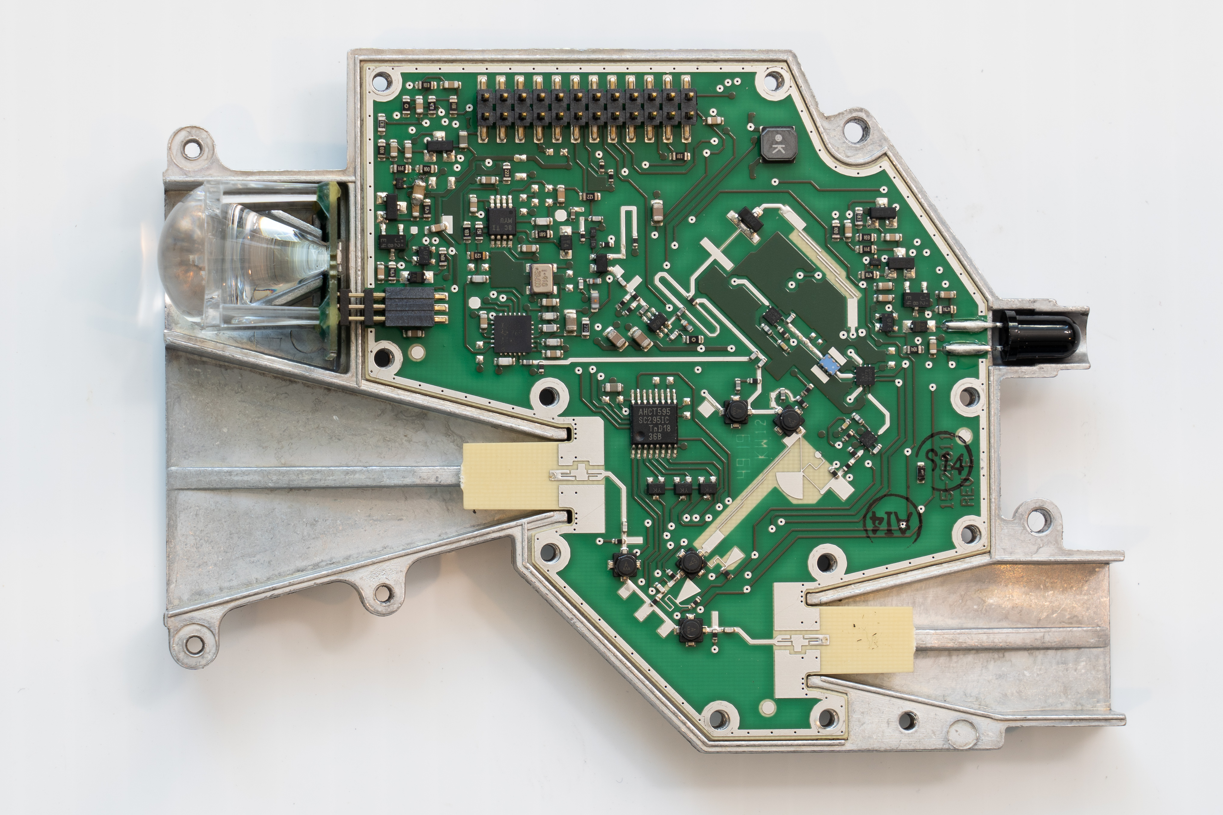
The RF PCB is dual sided as well, jam packed with circuitry. You’ll also see the black diode below sticking out the side which is the separate rear laser sensor.
On the board just below the black laser diode you’ll see the Revision E stamp for the PCB.
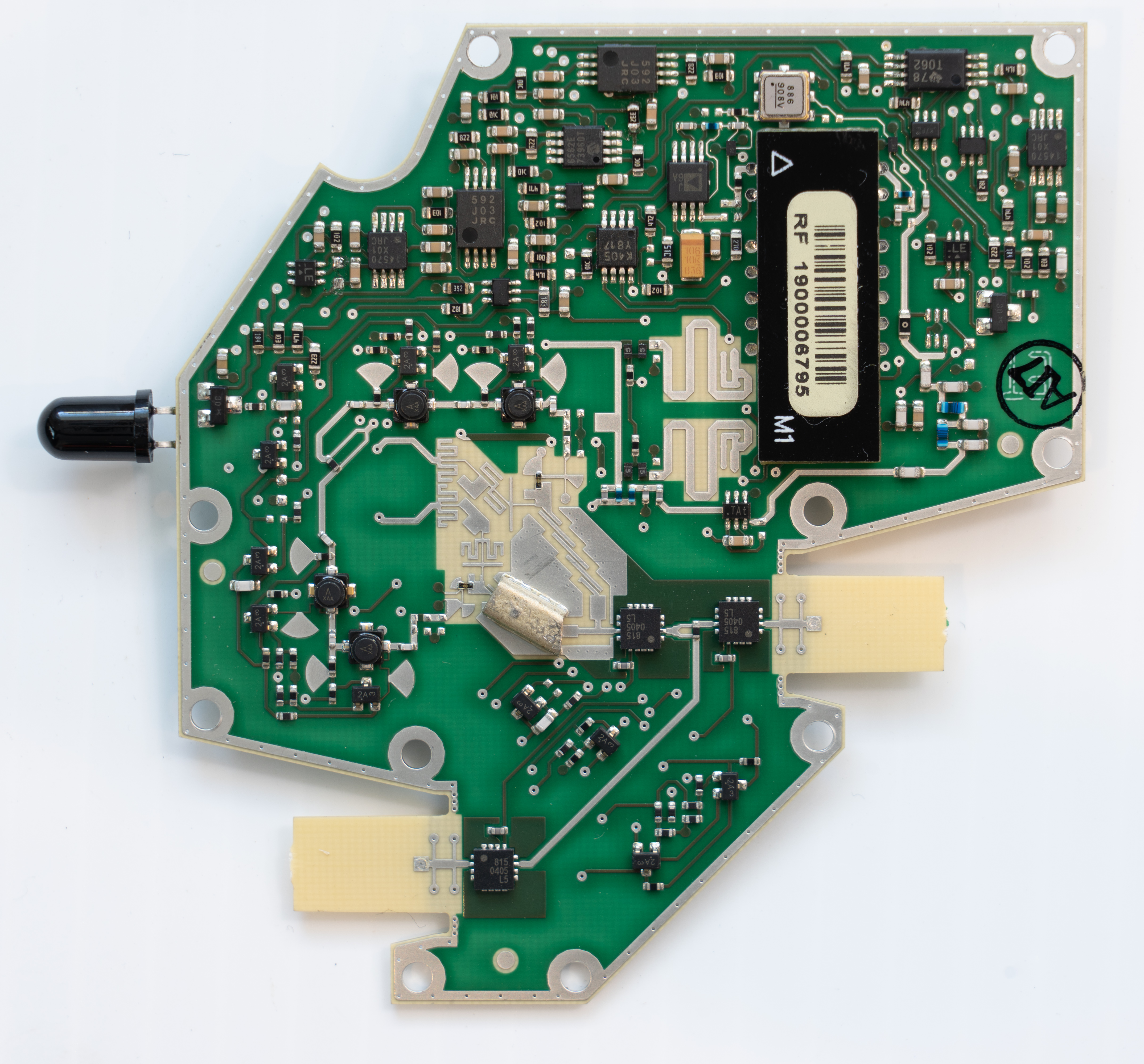
Sitting just behind the horns are the LNA’s (low noise amplifiers) that both help amplify and boost the incoming signal to give the V1 longer detection range and also help give the V1 it’s undetectability to the Spectre RDD. One side features front and rear LNA’s for X/Ku, the other side handles K/Ka.
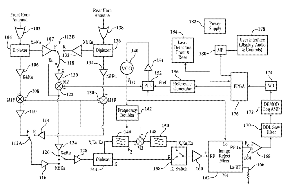
To make things a little easier to walk through, here’s a look at the V1 Gen2’s block-level diagram from the High probability of intercept radar detector patent.
That’s a quick teardown of the V1 Gen2! If you notice some other cool tidbits and points of interest to note, please let me know down in the comments. 🙂
You can purchase your V1 Gen2 here.
| This website contains affiliate links and I sometimes make commissions on purchases. All opinions are my own. I don’t do paid or sponsored reviews. Click here to read my affiliate disclosure. |


3 comments
Vortex I don’t see any messy soldering
Do you .?
Author
Nope, mine looks pretty clean.
My gen 2 will not stay on when I start my car.. I have to push the power button every time I start the car. I called valentine and they said this was a glitch with some of their units. They are sending me a fed x label to ship it back for repair.